
Bushing Monitor

Power Transformer Safe

The most relevant monitoring devices for keeping a power transformer safe are :
• Partial Discharge Detection – UHF method
• Bushing Monitoring
• Dissolved Gas Analysis
• Optical Vibration Sensing
• Tap Changer Monitoring
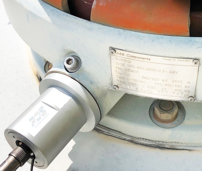
PDS’s EZY on-line Bushing Monitoring
PDS’s EZY on-line Bushing Monitoring measures the relevant parameters in situ with bushings energized, and measures the current phasor of each bushing, and the harmonics of each current (=capacitance and relative dielectric loss (tangent delta) of the bushing insulation) in order to reveal possible defect in advance.
Main Components
• EZY Tap :
Connecting plug
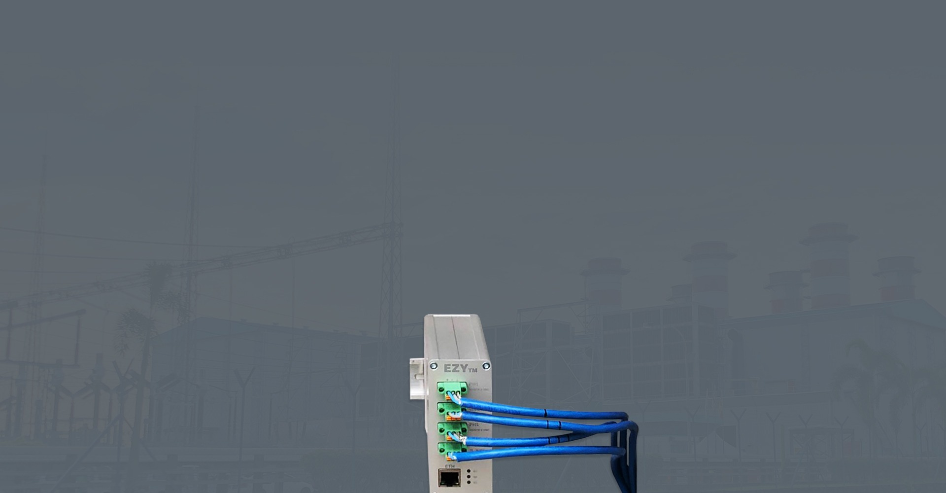
• EZY TM :
Data acquisition unit
• EZY Software :
Monitoring software for display and MMI
• EZY Pad :
Local data display unit (optional)
The User Interface
-
1. Phasors Diagram
It shows the instantaneous currents of each phase and the summed currents in angular domain. Note: The NETT (sum of current) vector shown is post multiplied 10 times for visual amplification purpose.
-
2. Phasor Magnitudes Trend
It shows the magnitude trends of the current of each phase over the last hour.
-
3. Sum of Current Magnitude Trend
It shows the magnitude trend of the unbalanced current, and the alarm thresholds.
-
4. Alarm Table
Shows the active and inactive alarms, and allows user to act on them. Button functions are listed in table below.
-
5. Offline Data
It shows the initial bushing capacitances of each phase and allows user to adjust after offline test.
IO :
| Number of galvanic isolated channels | 3 |
| Power supply | 18-36 VDC or PoE |
| Communication | Ethernet RJ45 |
Single Channel specifications :
| CMMR to 50Hz with 1kOhm Imbalance | 98dB |
| Gain drift | 10ppm/°C |
| Offset drift | 1.7uV/°C |
| Distortion | -100dB THD at 1kHz -3 dB Bandwidth: 10MHz |
| Post voltage divider Input Impedance | 5.3 Gohm , 0.5pF |
| Input voltage divider Impedance | 83.827 kOhm |
| Maximum Differential Overvoltage | 50V RMS |
| Selectable analog nominal Input Voltage ranges | 1,2,5,10 V RMS |
| Selectable analog pre sampling -3dB LP filters | 2.5,25,50,100 kHz |
| Application specific sampling Frequency | 84 kHz |
| Maximum sampling Frequency | 466 kHz |
Single Channel to internal GND insulation :
| Rated Insulation Voltage | 5000 Vrms / 1-minute duration |
| Maximum working insulation voltage | 565 V peak |
| Transient Overvoltage,tr=10 sec | 7070 V peak |
Mechanical properties :
| Weight | 480g |
| Dimension | (h,w,d):107x46x103mm |
| Mounting | DIN Rail |